Logic Gate Commutation
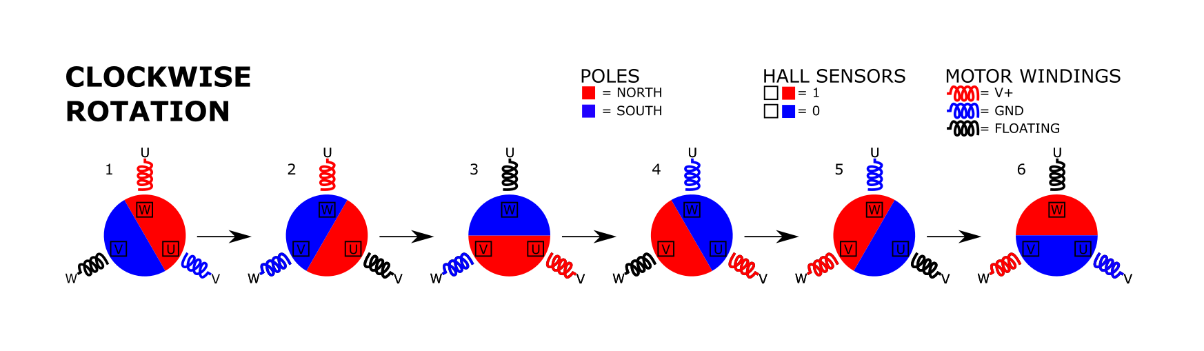
Now it is time to start spinning the motor. BLDC drives and algorithms are said to be complex and take too much time to learn and implement. Well, let us try to simplify them. The simplest way to commutate a BLDC is with trapezoidal BEMF and using hall sensors to sense rotor position. In order to reduce complexity of coming up with an algorithm, the motor construction will be simplified. The motor will have 1 pole pair (1 SOUTH and 1 NORTH pole) and only one coil for each winding. For trapezoidal commutation two coils are passing current. One coil is connected to V+ and the other to GND. The current through the windings will create a magnetic field. The coil which V+ is connected to will create a NORTH pole and the coil which is connected to ground will create a SOUTH pole. The hall sensors sense magnetic fields. There are analog and digital halls. I will be using digital halls and they will either output a 1 or a 0. When the SOUTH pole of a magnet is next to the hall sensor, the hall sensor will conduct. Hall sensor ICs are usually open collector and there are pull ups connected to them in order to sense changes. In other words, if there is a south pole next to the hall sensor, the collector will be a switch to ground. The output will be a 0. If there is a NORTH pole or nothing next to it then the pull up will do its job and have a 1 on the collector. With this information in mind, we get the following six steps to spin the motor. This is a clockwise rotation when looking at the motor shaft.
In order to connect each winding to ground and V+, a half bridge is used for each phase. One FET is connected from V+ to the (high FET) and the other from the winding to ground (low FET). These are both NFETs in order to maintain similar RDSON, switching characteristics, and current capabilities. This also means they are matched.
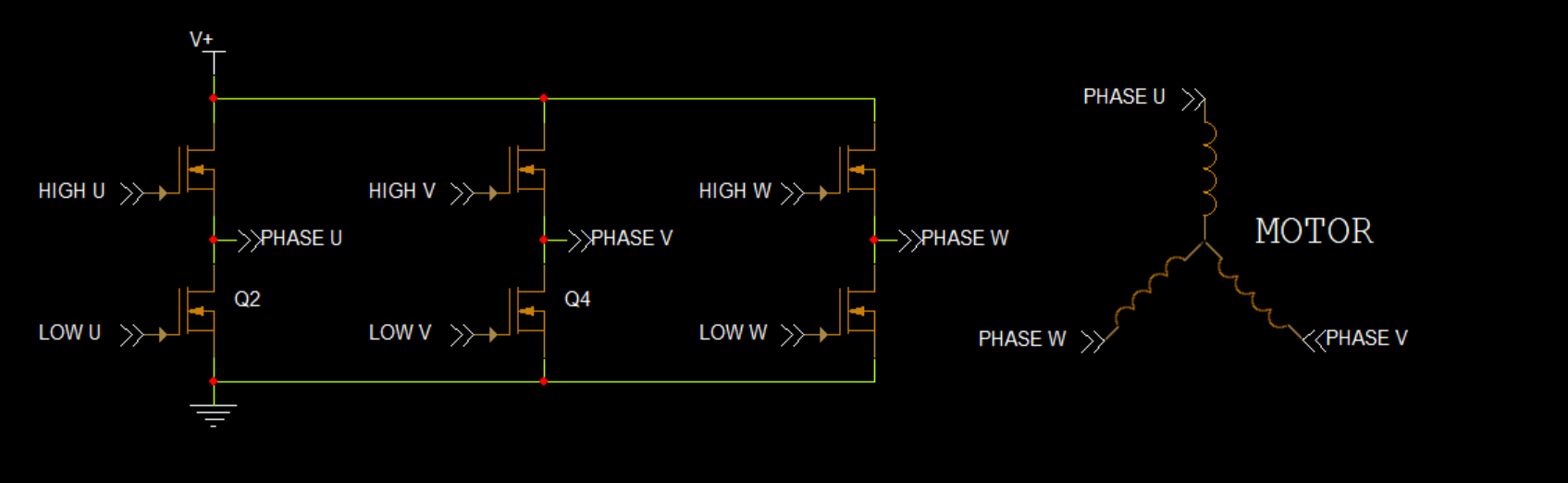
With this half bridge and the graph up top the following table can be derived.
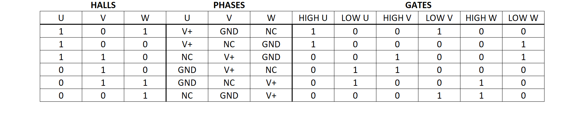
Using this table it is obvious that a trapezoidal drive with hall sensors can be implemented with just logic gates for the algorithm. Each gate depends on two out of the three hall sensor inputs. Let us look at HIGH U to prove this.
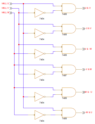
Looking at this table, it is apparent that HIGH U is 1 only when HALL U = 1 and HALL V = 0. At no other point in the table is HALL U = 1 and HALL V = 0 with HIGH U not being 1. This can be done for each gate FET. With & representing an AND gate, and ! representing NOT gate.
| FET GATE | EQUATION |
|---|---|
| HIGH U | HALL U & !HALL V |
| LOW U | !HALL U & HALL V |
| HIGH V | HALL V & !HALL W |
| LOW V | !HALL V & HALL W |
| HIGH W | HALL W & !HALL U |
| LOW W | !HALL W & HALL U |
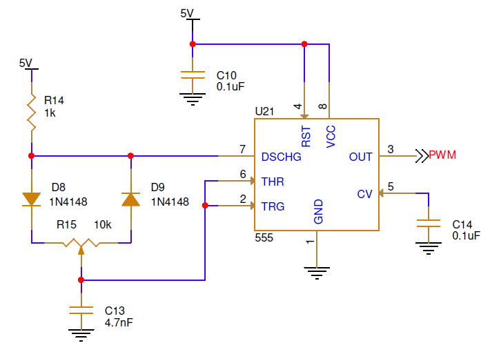
Using only this circuit, the motor will spin at one speed and be the fastest it can be with the provided power supply. Consequently, it will cause the currents to shoot up really high. This can be avoided by using lower voltages and increase the voltage to increase speed. To control voltage the most commonly done with PWM. PWMing the gates of the FETs will create different voltages across the coils. In the spirit of making this controller really simple, a 555 timer will be used. I am not going to go into details of it, but here is the circuit. Its PWM is from 10 to 99% and frequency at around 18kHz just like most BLDC drives. See the circuit used below.
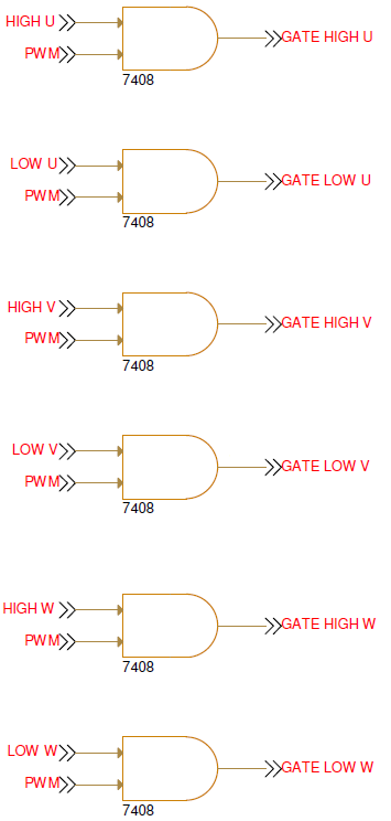
THe PWM and gate logic circuits have to be integrated somehow. For each gate, the gate logic output and PWM signal are put together using an AND gate. This is shown below.
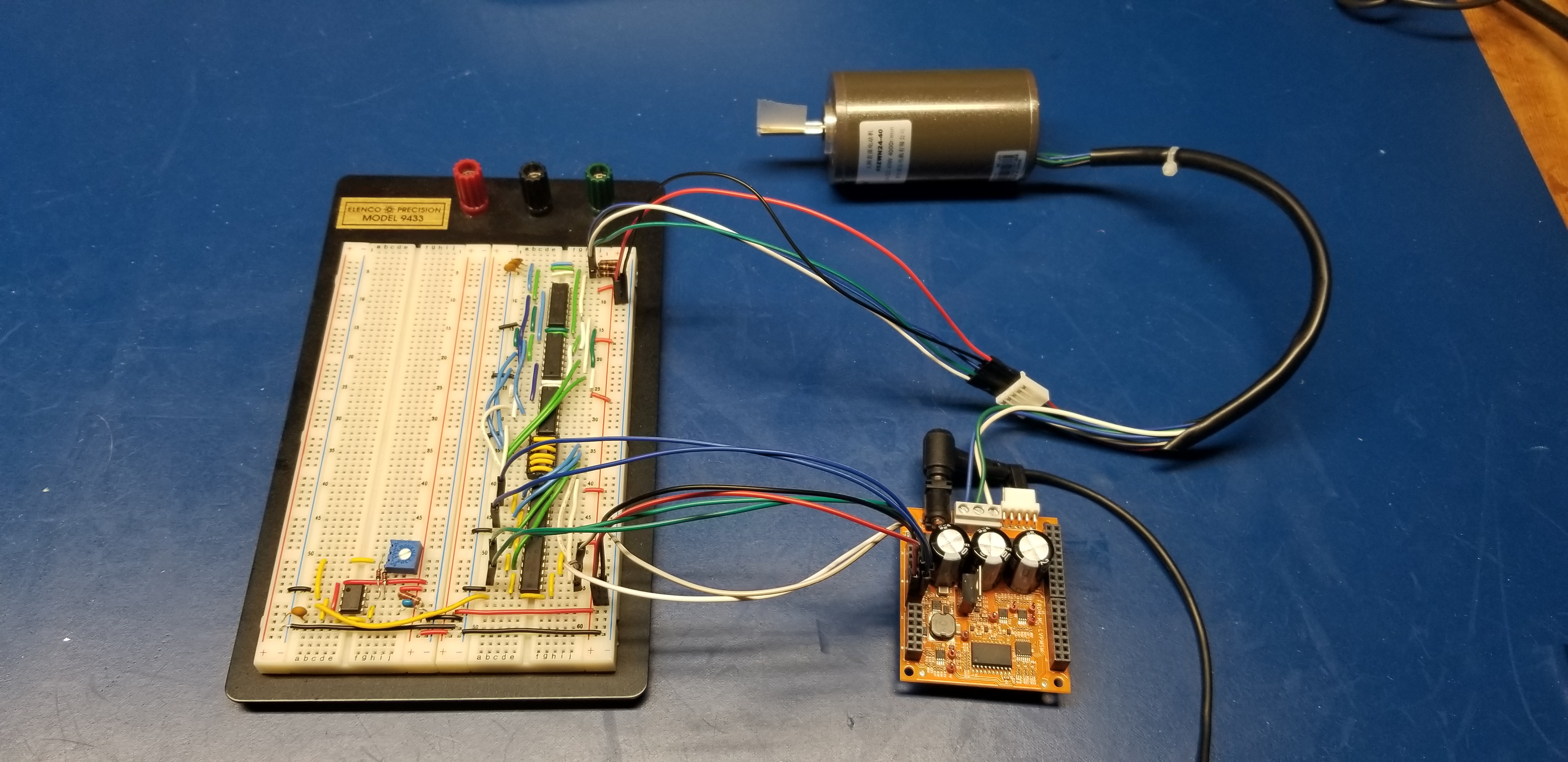
Being lazy and wanting to do it now, a BLDC motor and a dev kit from NXP was used. The FRDM-MC-LVPMSM driver board (only has gate drivers, FETs, 5V, and feedback) and Linix 45ZWN24-40 motor was used. The FRDM-MC-LVPMSM board is supposed to connect to another FRDM board with a micro on it. Since I am not using a micro, I connected this to a breadboard with the circuit above. I connected the halls directly to the breadboard which had pull up resistors of 10k and capacitor to ground of 0.1uF. The outputs of the AND gates were connected to the corresponding pins on the dev kit. I also used the 5V coming from the dev kit to power the logic gates on the breadboard. The dev kit had the motor phase wires connected and a plug with 24V on it.
Well, it didn’t work right away. There was a bunch of troubleshooting I had to do. All of it was human error. I will write another post about how to make sure everything is wired correctly along with how to troubleshoot some BLDC issues. Let’s not focus on that here, because this post is already getting too long. One thing to say here, however, is that if the connections aren’t right then either the magic smoke comes out or the motor does not spin. I took some scope shots of the driver in action at full speed or 99.3% PWM. I varied the drive but it looks best at full speed.
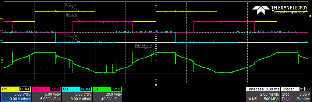
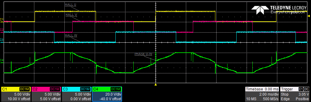
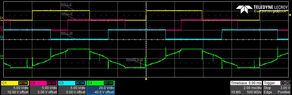
The top has halls and phase UV, mid has halls and phase UV, and last has halls and phase VW. Looking back at the table, it is correct. In conclusion, creating an algorithm for commutation with logic gates is possible and is relatively easy. In the next post, I am going to look at spinning the motor counterclockwise and will combine the two. Again, let me know if there are any mistakes or issues.
Updates: 04/29/2020 - Fixed broken link for breadboard picture, added HIGH U table look picture, fixed hall sensor positions on graph showing the motor spin, cleared up some sentences, fixed up grammatical errors.