Logic Gate Commutation Counter Clockwise
In the previous post logic gates were used to commutate a BLDC motor in the clockwise direction. Now let’s take a look on how this would work if we wanted the motor to spin counter clockwise. Just like in the previous post I made a graph of how the motor would spin counter clockwise.
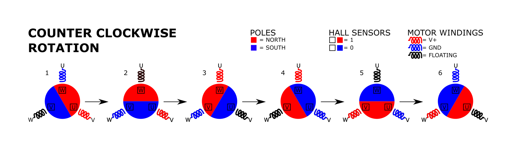
With the graph from the top you can derive the following table.
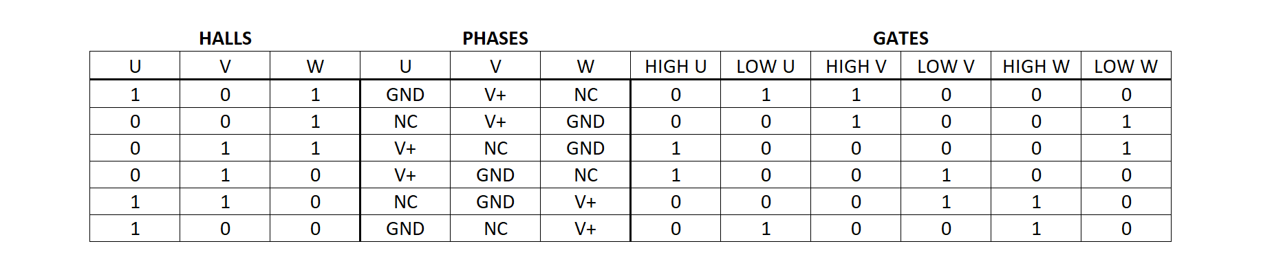
Like in the previous post lets look at HIGH U gate.
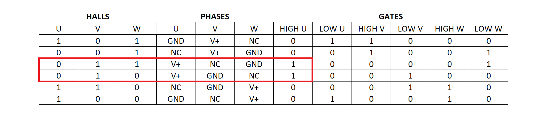
HIGH U is only 1 when HALL U = 0 & HALL V = 1. In no other time at the table is HALL U = 0 and HALL V = 1 with HIGH U not being 1. With & representing an AND gate, and ! representing NOT gate. The table is going to show all the gate equations.
| FET GATE | EQUATION |
|---|---|
| HIGH U | !HALL U & HALL V |
| LOW U | HALL U & !HALL V |
| HIGH V | !HALL V & HALL W |
| LOW V | HALL V & !HALL W |
| HIGH W | !HALL W & HALL U |
| LOW W | HALL W & !HALL U |
This looks weirdly familiar. Almost exactly the same as the clockwise direction logic gate equations except the HIGH U was switched with LOW U, HIGH V with LOW V, and HIGH W and LOW W. Lets compare both equations side by side.
| FET GATE | CW EQUATION | CWW EQUATION |
|---|---|---|
| HIGH U | HALL U & !HALL V | !HALL U & HALL V |
| LOW U | !HALL U & HALL V | HALL U & !HALL V |
| HIGH V | HALL V & !HALL W | !HALL V & HALL W |
| LOW V | !HALL V & HALL W | HALL V & !HALL W |
| HIGH W | HALL W & !HALL U | !HALL W & HALL U |
| LOW W | !HALL W & HALL U | HALL W & !HALL U |
From the table comparing both directions we can see that the they use the same hall sesnsors execpt the polairty of the halls is fliped. Using the same exact circuit and breadboard from the previous except flipping the FET gates (low to high and high to low) we can test this out.
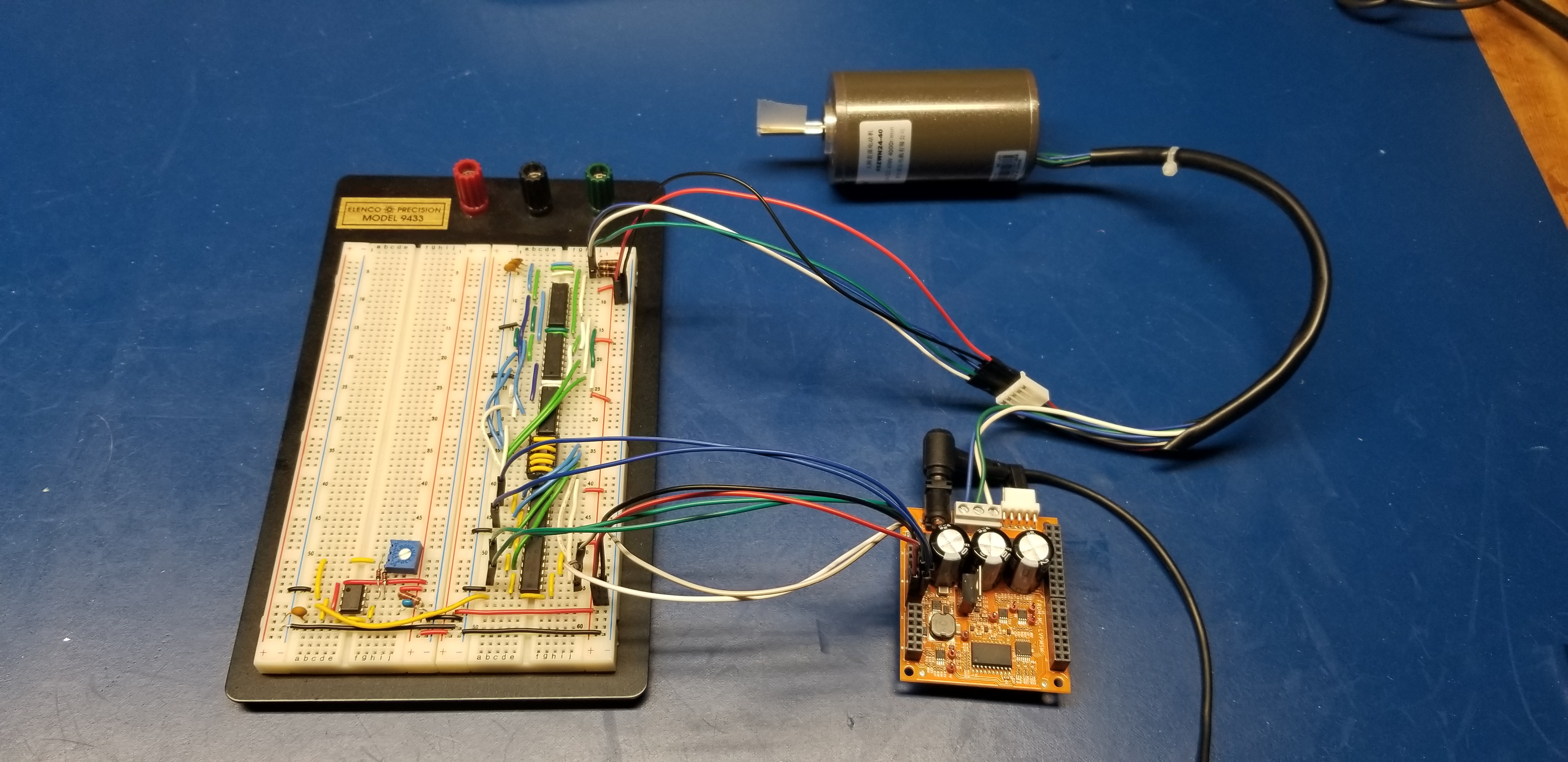
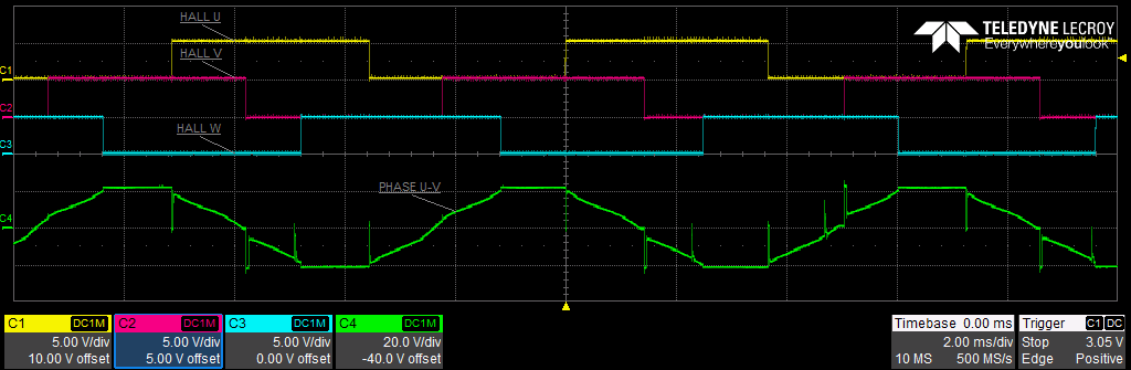
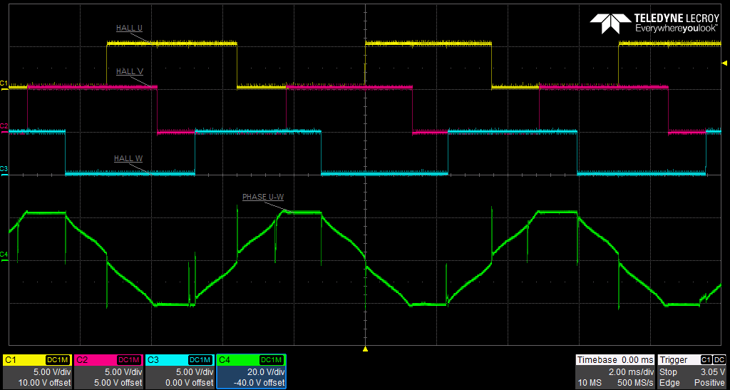
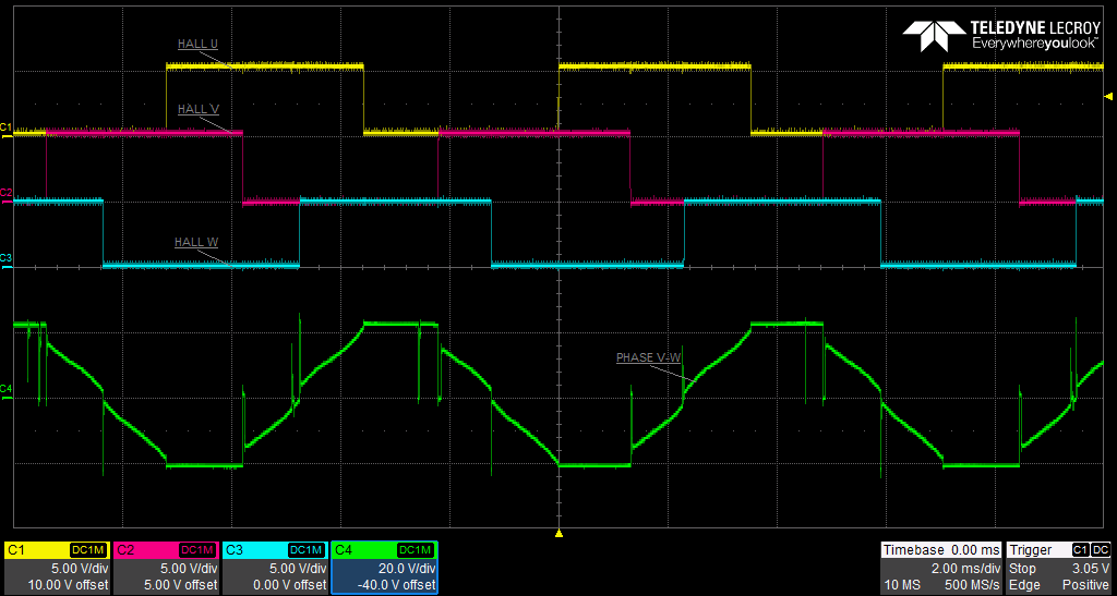
The motor spins in the other direction. Just to make sure this is correct lets us take some scope shots to verify all of this.
So with one circuit we can spin the motor clockwise and counterclockwise. This requires manual switching a bunch of wires. That is all I have for this post. Next post I will show my work on a PCB that will encompass these circuits. It will also just have a switch for changing directions.