Christmas Ornament
Some people say that hand made gifts are the best presents. So I decided to take sometime and make some ornaments for the tree. Being an electrical engineer my thought was to make it out of PCBs. To make sure the shape is easily manufacturable, I have picked the PCB shape to be a circle. I believe this will mimic an ornament the most. I did not want to overcomplicate the ornament on my first setup. This made me decide to just have a microcontroller, LEDs, battery, and a switch.
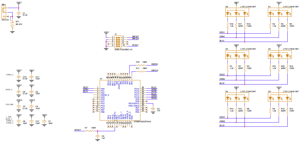
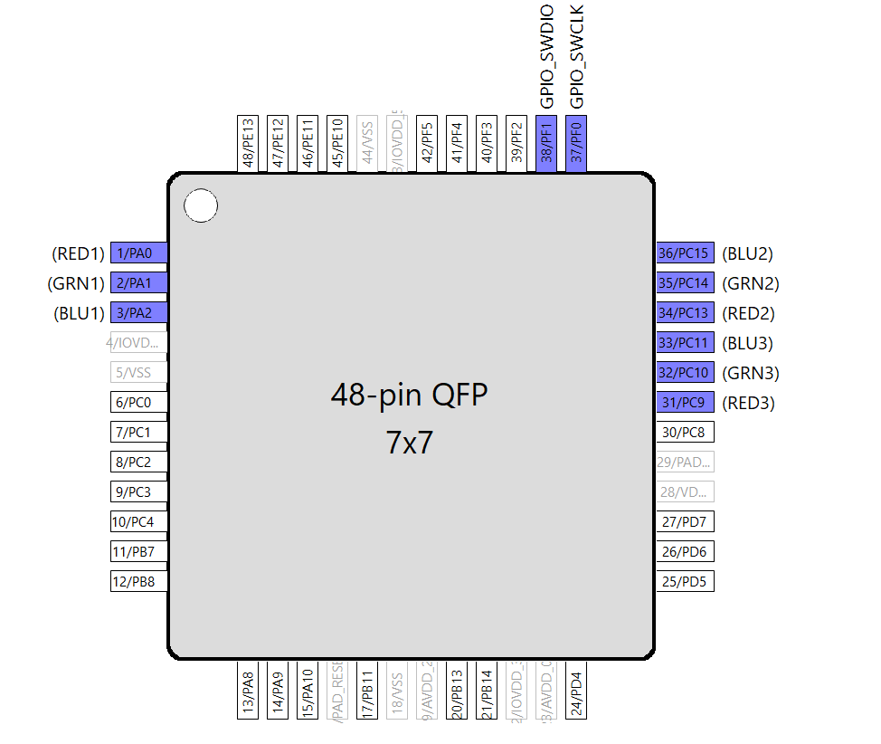
The EFM32HG222F64 microcontroller was picked, because I have lots of them to spare. This micro is definitely way over powered for this application. I downloaded the Simplicity Studio IDE to write firmware and configure the pins. Going through Simplicity Studio I “double checked” the pins I have picked. Originally I had planned of using timer peripheral for each LED pin, but on the schematic I missed one pin. BLU3 should have been on pin 32, GRN3 on pin 31, and RED3 on pin 30. I instead put them on 33, 32, and 31 (oops). THis prevents all LEDs not fully PWM’able. So I decided to just use the pins as GPIOs, maybe next year I will order new boards.
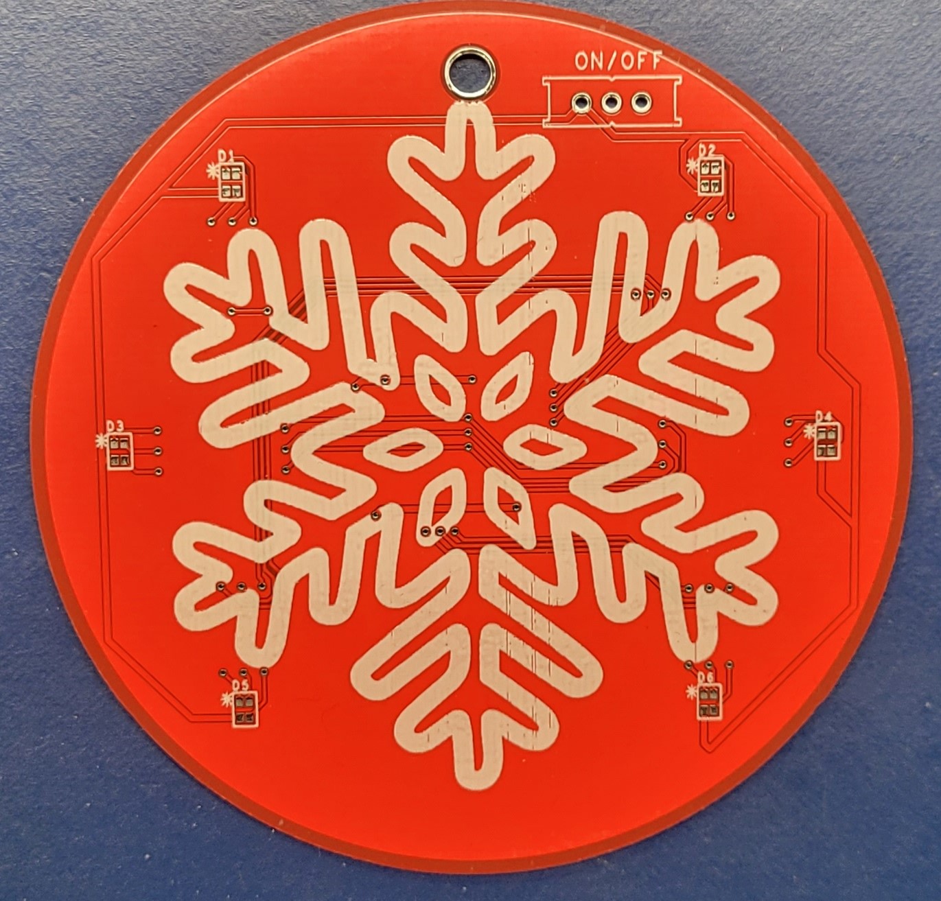
Now to go through other components. The switch and battery holder I have used before were inherited to the design. Why should you add new parts, when you can reuse and save time? The capacitors, resistors, and JTAG/SWD programmer are parts that I have used and info coming from datasheets/application notes. These values have been verified before and I have not ran into any issues using them. The only values that are of question now are the current limiting resistors for the RGB LEDs. I wanted to make sure that they would create a white color when all three RGBs are on. From past experience I know there needs to be a bit of calculation. Just setting them to 2mA for each LED will cause a purple color most likely. I will not go into much details as there is a lot of equations. Maybe I will include this on my second rev. This topic will be a whole post by itself. Now the last thing to do is to add some kind of Christmas silkscreen. I picked a snowflake since it is very fitting with white silkscreen. Importing it to the PCB editor took a little while, but I eventually got the thickness

With this all set I put my orders for PCBs and components. All I had to do was wait and maybe write a little bit of code. Within a week and a half I had my boards. Amazing how fast they are manufactured and delivered to your door from China. I think they came out pretty good.
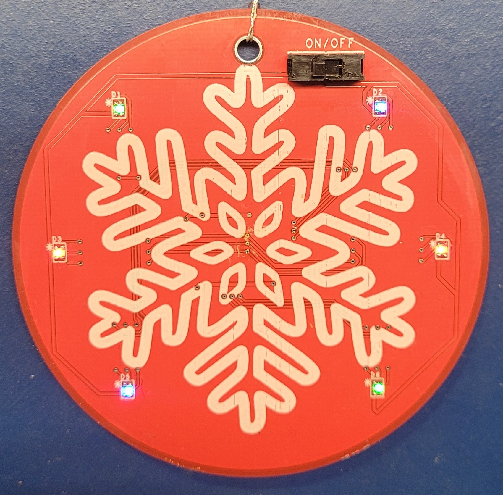
I got to work on soldering them. Went pretty fast since there were not a lot of parts to solder. Next I booted up Simplicity Studio and flashed the devices. I ran the debugger and no lights. I tested all the LEDs with my diode checker on the DMM. So what is going on. Well apperantly I forgot that the outputting 3.3V to an LED pin will not do anything. All the LEDs in the RGB are connected to 3.3V, so no currrent will flow if I output a high on the corresponding pin. Changing this to go low when I want an LED on fixed all my issues. I got the code to cycle through different colors. The LEDs can be the following colors: RED, GREEN, BLUE, YELLOW, TEAL, PURPLE, and WHITE. I made all LEDs first be one LED RED, GREEN, or BLUE. Since I have the RGBs in pair I only have two LEDs of the same color on. First three steps all LEDs cycle between those base colors. Then they cycle between YELLOW, TEAL, or PURPLE. Then all 6 RGBs turn WHITE. After this is done they go through that cycle again. Here is my finished product.
The gerbers and firmware are on my github page. They are free to use. I use OrCAD for schematic and layout so I have not included the design files. So I will not include them, because I doubt a lot of people have a license. I will happly share them if someone wants it. Just send me an email. I will try to revist this project in 2021 mid year. That way I can implement more features.